Quick Start Guide
In this example, you’ll learn to connect your database, set up a staging node with a data transformation, and create a dimension and fact table.
Before You Start
- Sign up for a Coalesce account.
- Make sure you're using Google's Chrome browser, as other browsers are not officially supported.
- Have your Snowflake login available. Don’t have a Snowflake account yet or not ready to connect your company’s Snowflake to Coalesce? Sign up for a free trial and use Snowflake’s provided sample data.
Video Overview
The following video provides a brief overview of what this guide covers.
Interface
When you first sign in on a new account, you'll be presented with the Projects Dashboard, that includes a default Project and Development Workspace. Click the Launch button to open the workspace to continue. You can ignore the version control warning since it won't be used in this guide.
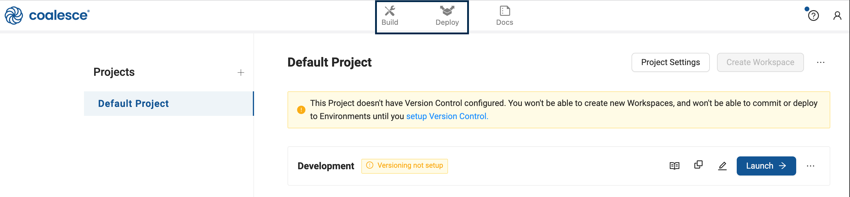
In the Development Workspace is the Build interface and Deploy interface.
The Build interface is where you'll create nodes, build node graphs, and transform your data. The Deploy interface is used to push your pipeline to other environments such as QA and production.
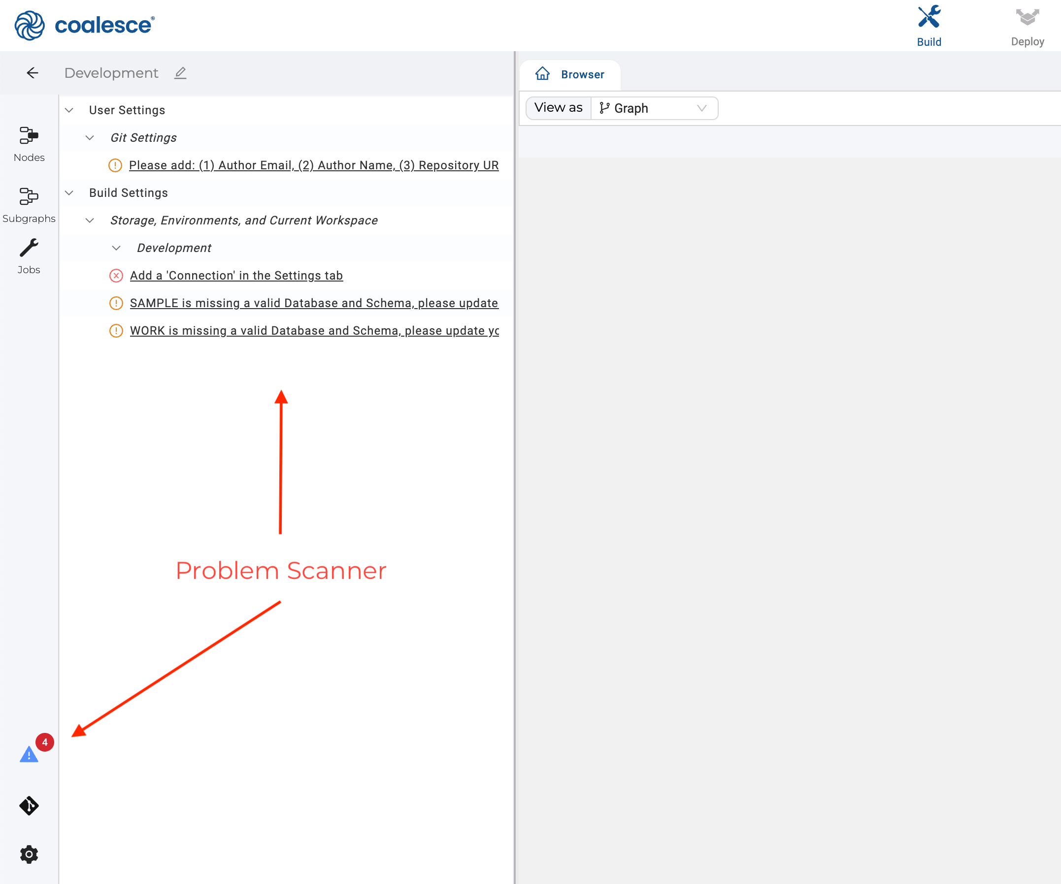
For new accounts, the Problem Scannerwill show a few action items. You can disregard them for this guide..
Connect to Snowflake
-
Click on Build Settings, which is represented by a cogwheel icon.
-
Go to Development Workspaces and edit your current Workspace by clicking the pencil icon to the right of it.
-
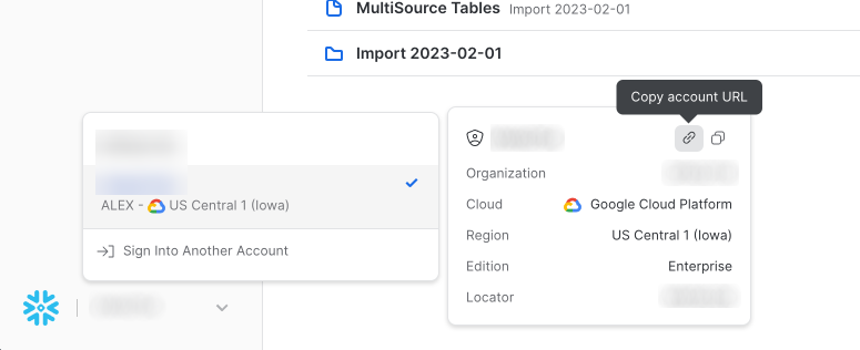
On the Settings page, enter your Snowflake Account.
- Obtain your Snowflake URL, by opening the account selector in Snowflake.
-
Go to User Credentials and fill out the form with your Snowflake login.
-
Click Test Connection to ensure your credentials work as expected.
-
Click Save.
You've now connected Coalesce to your Snowflake instance.
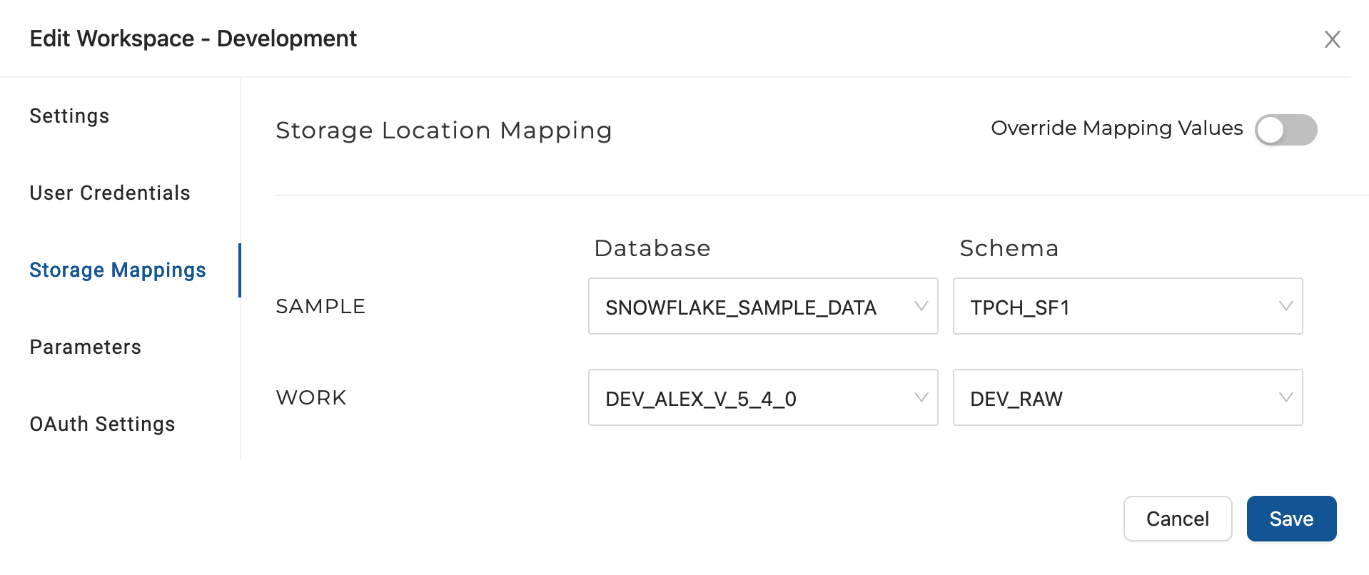
Configure Storage Locations and Workspace
A storage location is a logical name you provide to represent a database and schema (in Snowflake) and you will need them to make use of the Workspace you configured in Connect to Snowflake. Depending on your setup you may need to create a storage location in Snowflake.
- Go to Build Settings >Storage Mappings. You'll have a SAMPLE and WORK locations. The Snowflake Sample Data will be mapped to SAMPLE and the WORK is where you'll write new tables.
- Set the SAMPLE database to use the Snowflake sample data, and use the schema TPCH_SF1.
- Set the WORK to a second storage location and schema in that storage location.
Build a Transformation Pipeline
Now it's time to add Sources to the graph. The Node Graph is where you'll configure Nodes that will transform your data. Below is an example of a graph with several nodes. Each box is considered a Node.
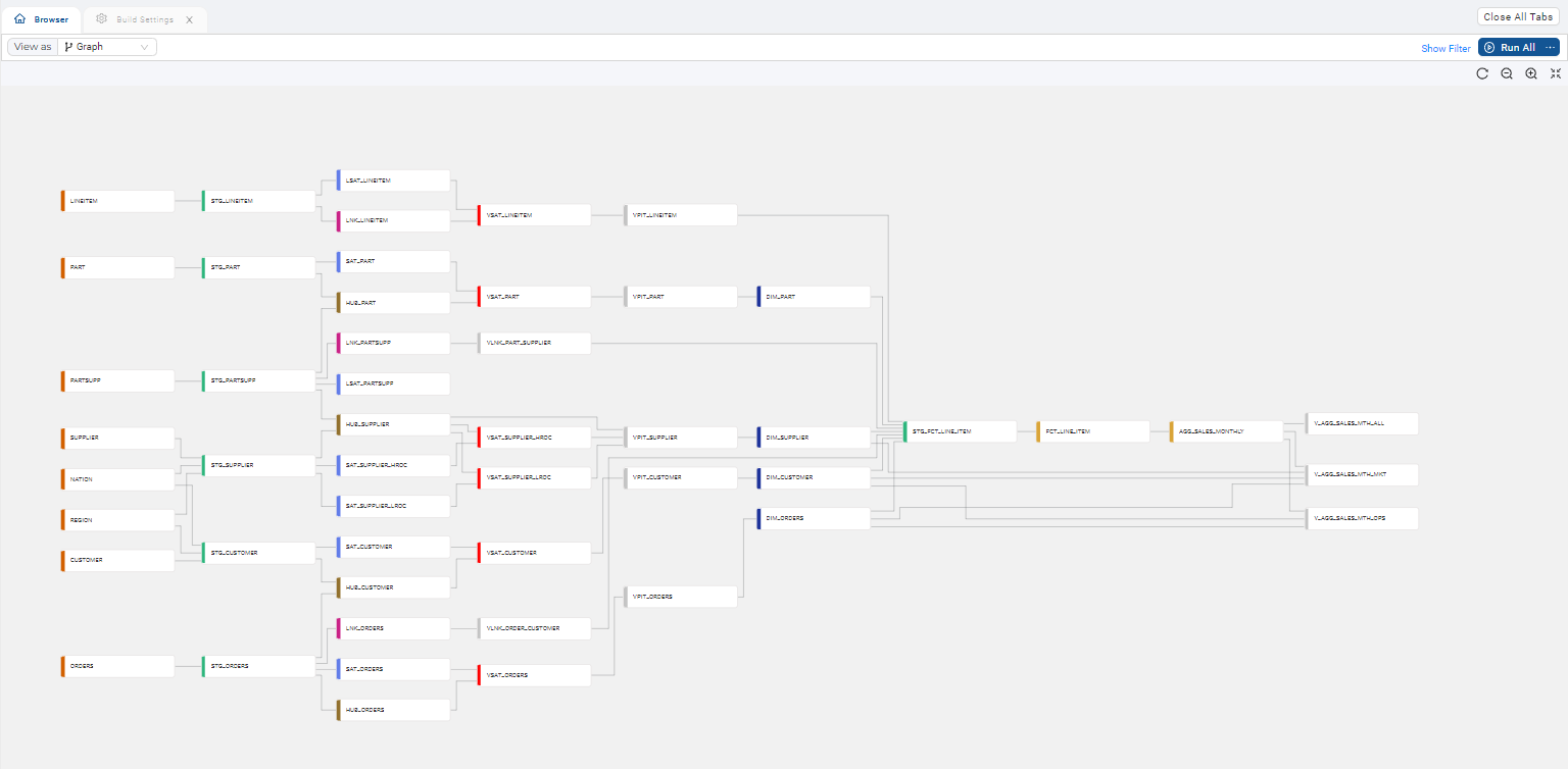
Add Graph Sources
- Expand Nodes from the sidebar.
- Click on the + next to Search > Add Sources.
- Choose your source tables and click Add Sources.
- You'll now see your graph populated with some Source Nodes.
Make a Stage Node to Transform Your Data
Now that you have Source Nodes on your graph, it's time to add a Stage Node. Stage Nodes are intermediate nodes in the graph where you can preview your changes.
- Add one or more Stage Nodes by right clicking your
NationSource Node>Add Node>Stage Node. You can select multiple Source Nodes by Shift+clicking them and then add multiple Stage Nodes simultaneously. - Double click on the Stage Node or right-click and select Edit to open up the Node Editor for the Nation Stage Node you created.
- Open Node Properties on the right and ensure the Storage Location is set to the WORK you configured earlier. You'll be writing to this location in Snowflake.
- Click Create to create a table in Snowflake. You'll see the status in the lower window.
- Click Run to populate the table. You'll see the status in the lower window. You haven't transformed the data yet.
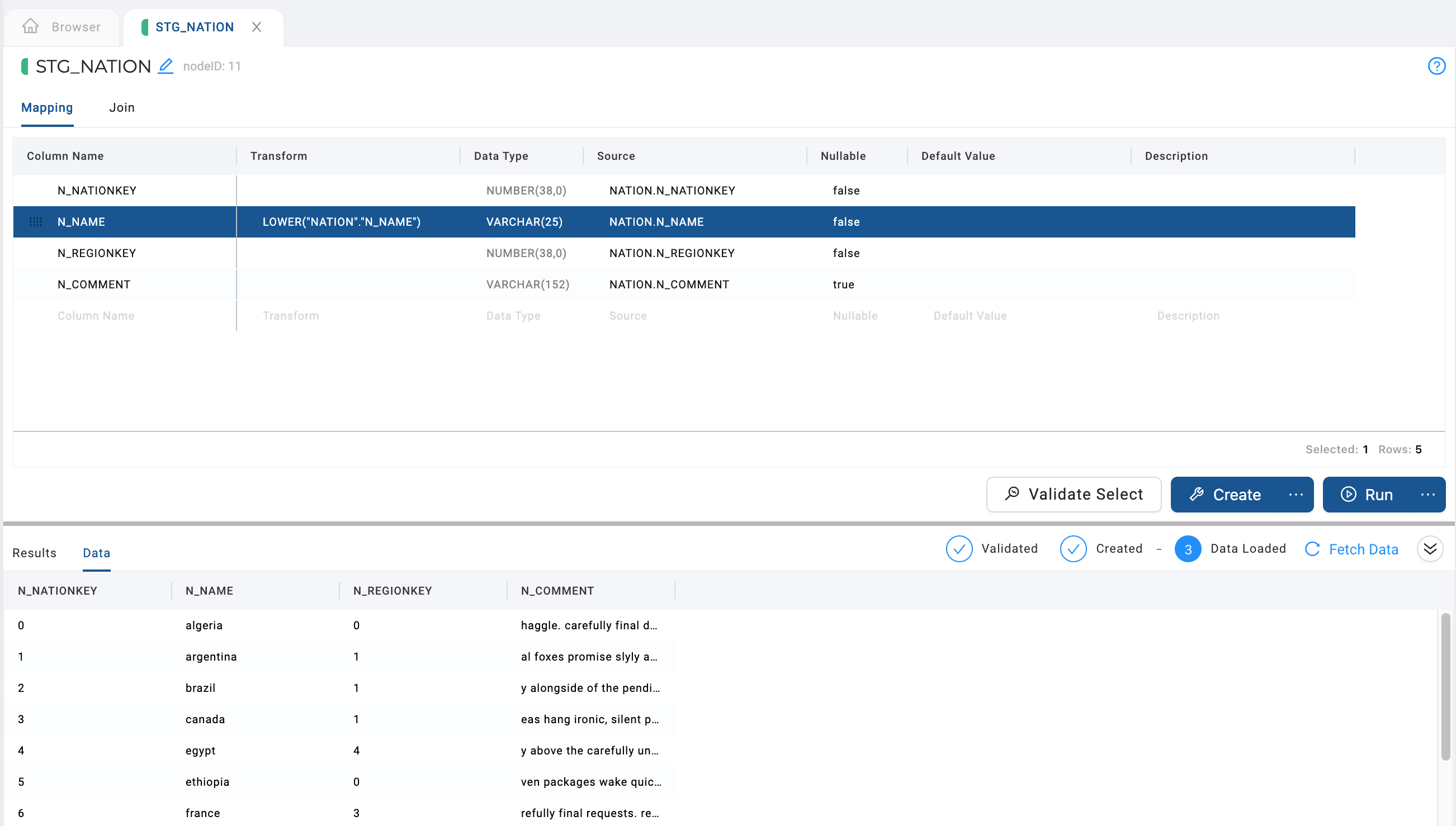
- Edit the Transform field in the Mapping grid by double clicking in the transform field of the
N_NAMEcolumn. Try a simple transform likeLOWER()and the name of your column, or you can use the syntaxLOWER("NATION"."N_NAME")to edit the Snowflake sample data. - Click Run again to transform the data. You'll see that the nation names are in lowercase.
Any Snowflake SQL transform can be used to transform your data.
Congratulations, you've connected your database and applied a basic transformation to your data. Feel free to continue experimenting with some of the other node types below.
Create a Dimension Table
In this guide we will be making a Type 2 Dimension to track historical data of a column. A slowly changing dimension(Type 2) is a industry standard for tracking historical data by creating multiple records for a given natural key.
By default, Coalesce creates a Type 1 Dimension, you'll add a Type 2 Dimension.
-
Right click on the
CUSTOMERnode and create a new Stage Node. -
In the Node editor for
STG_CUSTOMER, click Create and then Run. -
Return to the main graph and create a Dimension node from the
STG_CUSTOMERnode.
-
Go into the new
DIM_CUSTOMERNode editor. -
Open up Options and select
C_CUSTKEYas a business key by selecting it and clicking the right arrow. -
In the same Options area, go to Change Tracking and select
C_ADDRESSandC_PHONE, then click the right arrow to add them. -
Now Create and Run the
DIM_CUSTOMERnode. Congratulations. You've created a Type 2 Dimension table.
In the Dimension Node, if no Change Tracking columns are selected, the node will act as a Type 1 Dimension. If Change Tracking columns are selected, it will act as a Type 2.
Create a Fact Table
Now let's create a fact table. You're joining the Orders (STG_ORDERS) with the Dimension table on the DIM_CUSTOMER_KEY and ORDERS Customer key. Then you'll create a Fact table of the customers and orders. Because you're specifying the O_ORDERKEY, it will merge instead of inserting the data.
-
Create a new Stage Node from the
ORDERSSource Node. -
Open the new
STG_ORDERSnode and delete all the columns except forO_ORDERKEY,O_CUSTKEY, andO_TOTALPRICE. You can drag and drop rows to group the items for deletion. -
Select the
DIM_CUSTOMERnode on the left side, then selectDIM_CUSTOMER_KEYand drag it into yourSTG_ORDERSmapping grid.
-
Go to Join, next to Mapping in the
STG_ORDERSNode Editor. -
Delete any existing text.
-
Click Generate Join and then Copy to Editor.
-
Replace the
/_COLUMN_/text withO_CUSTKEY. It should look similar to the following:FROM {{ ref('SAMPLE', 'ORDERS') }} "ORDERS"
LEFT JOIN {{ ref('WORK', 'DIM_CUSTOMER') }} "DIM_CUSTOMER"
ON "ORDERS"."O_CUSTKEY" = "DIM_CUSTOMER"."C_CUSTKEY" -
Create and Run the
STG_ORDERSnode. -
Create a Fact Node from
STG_ORDERS. -
Open the new
FCT_ORDERSNode Editor. -
Open Options > Business Key > add the
O_ORDERKEY -
Create and Run the
FCT_ORDERSnode.
Congratulations. You have now made a fact table. You can also run this query in Snowflake. Make sure to adjust your schema(MY_SCHEMA) and database(MY_DB) to your environment.
select DIM.C_NAME CUSTOMER_NAME,
sum(FCT.O_TOTALPRICE) TOTAL_PRICE
from "MY_DB"."MY_SCHEMA"."FCT_ORDERS" FCT
inner join "MY_DB"."MY_SCHEMA"."DIM_CUSTOMER" DIM
on FCT.DIM_CUSTOMER_KEY = DIM.DIM_CUSTOMER_KEY
group by DIM.C_NAME;